| Part No. |
Part No. |
Part No. |
Part No. |
| BZZ1-100A |
BZZ1-200B |
BZZ1-400C |
BZZ5-200B |
| BZZ1-100B |
BZZ1-200C |
BZZ1-500A |
BZZ5-400B |
| BZZ1-100C |
BZZ1-250A |
BZZ1-500B |
BZZ5-500B |
| BZZ1-125A |
BZZ1-250B |
BZZ1-500C |
BZZ5-630B |
| BZZ1-125B |
BZZ1-250C |
BZZ1-630A |
BZZ5-800B |
| BZZ1-125C |
BZZ1-350A |
BZZ1-630B |
BZZ1-1000A |
| BZZ1-160A |
BZZ1-350B |
BZZ1-630C |
BZZ1-1000B |
| BZZ1-160B |
BZZ1-350C |
BZZ1-800A |
BZZ1-1000C |
| BZZ1-160C |
BZZ1-400A |
BZZ1-800B |
BZZ5-1000B |
| BZZ1-200A |
BZZ1-400B |
BZZ1-800C |
|
| Appliion |
Used for Heli H2000 series CPCD20~30 |
| |
Used for Heli H2000 series CPCD50~100,
Baoli CPCD50~100 |
| |
Used for Hc H series CPCD20~35 |
| |
Used for Hc R series CPCD50~70 |
| |
Used for Hc R series CPCD40~50 |
| |
Used for Hc XF series CPQD30~35 |
| |
Used for Tcm FD20~30T6,Teu FD20~30
etc.
|
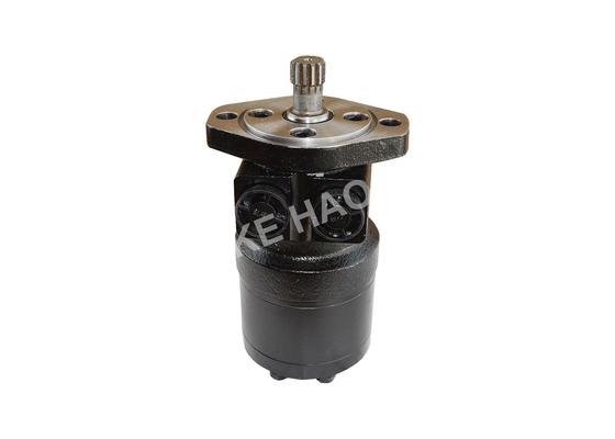
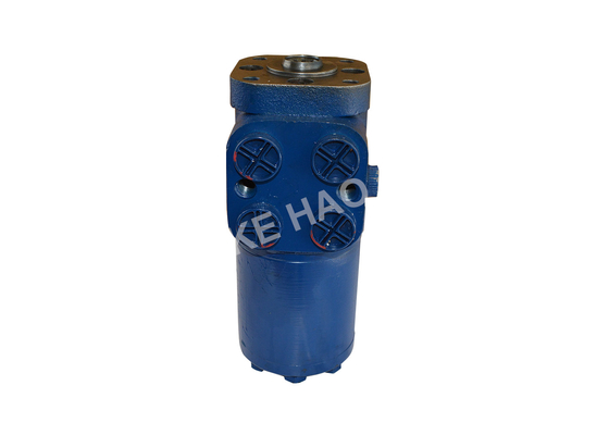
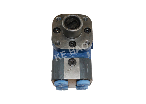
The full-hydraulic steering gear is a hydraulic power steering type which is connected between the steering wheel and the steering control mechanism, does not need to be connected with a connecting rod, has the advantages of light and flexible operation, simple structure, low price, convenient installation and arrangement of the complete machine and the like. At present, the cycloid type full-hydraulic steering gear is widely used at home and abroad.
The full hydraulic steering gear is a kind of hydraulic power steering type which does not need to be connected with connecting rod between the steering wheel and the steering control mechanism. it has the advantages of light and flexible control, simple structure, cheap price and convenient installation and arrangement of the whole machine. At present, cycloid full hydraulic steering gear is widely used at home and abroad.
The operating principle of the BZZ full-hydraulic steering gear (taking the BZZ1 type as an example) can be understood from the hydraulic function diagram of the full hydraulic steering gear (as shown in FIGS.1 and 2). It is easy to see that the working state of the steering gear is divided into the neutral state from the hydraulic function diagram. The left-turn and right-turn states are 3 working conditions.
When the steering gear is in the middle position, the valve core and the valve sleeve are in the middle position under the action of the spring piece, the oil from the oil pump is inserted into the interior of the valve core through the valve sleeve and the valve core end 2, and then flows back to the oil tank by the oil port T.
When the steering wheel turns to the right (or left), drive the valve core to turn right (or left). Because there is a maximum rotation of 10.5 °between the valve core and the valve sleeve, the valve core will overcome the elasticity of the spring between the valve core sleeve and the valve core sleeve, so the valve core will rotate relative to the valve sleeve. At this time, the valve core oil groove is connected to the inlet circuit of the valve sleeve, and the oil supply of the pump flows from the valve sleeve to the rotor and stator, pushing the rotor to rotate relative to the stator, at the same time, The oil outlet between the rotor and the stator passes through the valve sleeve and enters one cavity of the steering cylinder through orifice A (or B), so that the piston rod of the cylinder extends (shrink) and the steering wheel turns to the right (or left), and the oil of the other cavity of the cylinder goes from the oil orifice B (or A) to the oil orifice B (or A). After entering the valve sleeve and passing through the return tank of the valve core, the oil return hole of the valve sleeve passes through the oil port T to return the fuel tank, so as to realize the steering function.
When the relative rotation angle of the valve core valve sleeve is about 1.5 °, the oil path begins to be turned on, and the rotation of the rotor leads the oil to the cylinder, and the amount of oil supplied is proportional to the rotation angle of the steering wheel.
When the steering wheel turns to the right (or left) at the same angle, the oil-driven rotor of the oil pump also turns to the right (left) due to the opening of the above oil channel. When the rotation angle of the rotor is the same as that of the steering wheel, because the valve sleeve and rotor are connected by coupling shaft and pin machinery, the rotor drive valve sleeve also rotates to the right (or left) at the same angle as the steering wheel. At this time, the valve sleeve and the valve core form a position without relative rotation angle, the oil channel leading to the rotor and cylinder is closed, so that the oil outlet of the oil pump enters the valve core through the valve sleeve and the 2 rows of small holes at the end of the valve core, and flows back to the fuel tank through the oil return hole of the valve sleeve. At this point, the tires Also stop the rotation, that is, hydraulic feedback follow-up action.
When the engine flameout or the steering oil pump fails (when the steering pump fails (when the steering wheel is turned by hand), the steering wheel can be steering under static pressure. When the steering wheel is turned right (left), the valve core turns at an angle of 10.5 °, and the valve sleeve, coupling shaft and rotor are driven by the dialing pin. When the rotor and the stator act as the pump, the rotor will be sucked out through the oil port T, through the one-way valve, the valve sleeve, and the valve core into the oil inlet cavity of the rotor pump. Due to the action of the hand rotating rotor pump, the oil produces pressure to enter one cavity of the steering cylinder, so that the piston rod extends (shrink), the wheel turns right (left), and the oil of the other cavity passes through the valve sleeve from the oil port B (A), and then the valve core. From the valve sleeve through the one-way valve to the rotor pump oil intake cavity, constantly fill in the large (small) cavity, to achieve steering.
Note: in order to ensure the realization of manpower steering, the steering gear should not be installed above 0.5 m above the liquid level of the tank in order to improve the oil absorption effect.

 Your message must be between 20-3,000 characters!
 Please check your E-mail!
  Your message must be between 20-3,000 characters!
 Please check your E-mail!
